Inverters
Inverters are devices that convert direct current (DC) into alternating current (AC), allowing DC sources like batteries or solar panels to power AC-based devices and systems.
History of inverters
The history of inverters is closely tied to advancements in electrical engineering and technology. Inverters are devices that convert direct current (DC) into alternating current (AC), allowing DC sources like batteries or solar panels to power AC-based devices and systems. Here’s a brief overview of the history of inverters:
- Late 19th Century – Early 20th Century: The concept of converting DC to AC was explored in the late 1800s. Engineers like Nikola Tesla and Charles Proteus Steinmetz made significant contributions to alternating current theory and technology. Tesla’s work on AC power systems laid the foundation for the development of AC-based power distribution.
- Mid-20th Century: The development of solid-state electronics paved the way for modern inverters. In the 1940s and 1950s, researchers began working on electronic devices that could efficiently convert DC to AC. This was especially important for applications like uninterruptible power supplies (UPS) and early telecommunications equipment.
- Late 20th Century: The advancement of semiconductor technology, particularly power transistors and thyristors (such as silicon-controlled rectifiers or SCRs), led to the creation of more efficient and reliable inverters. The development of pulse-width modulation (PWM) techniques allowed for better control of the AC output waveform, improving the quality of the inverted power.
- 1980s – 1990s: The growing demand for alternative energy sources and portable power solutions drove the development of inverters for various applications. Inverters became crucial components in renewable energy systems, powering devices in remote locations, and enabling the use of battery-powered electronics.
- 21st Century: Inverters continued to evolve with advancements in power electronics and digital control techniques. High-frequency switching and more sophisticated control algorithms improved the efficiency and performance of inverters. This led to the widespread adoption of inverters in solar power systems, electric vehicles, industrial automation, and more.
- Present and Future: Inverters are now integral to various technologies. They play a critical role in renewable energy systems, where solar panels and wind turbines generate DC power that needs to be converted to AC for grid integration. Inverters are also vital in electric vehicles, where they convert the DC power from batteries to AC power to drive the vehicle’s motor.
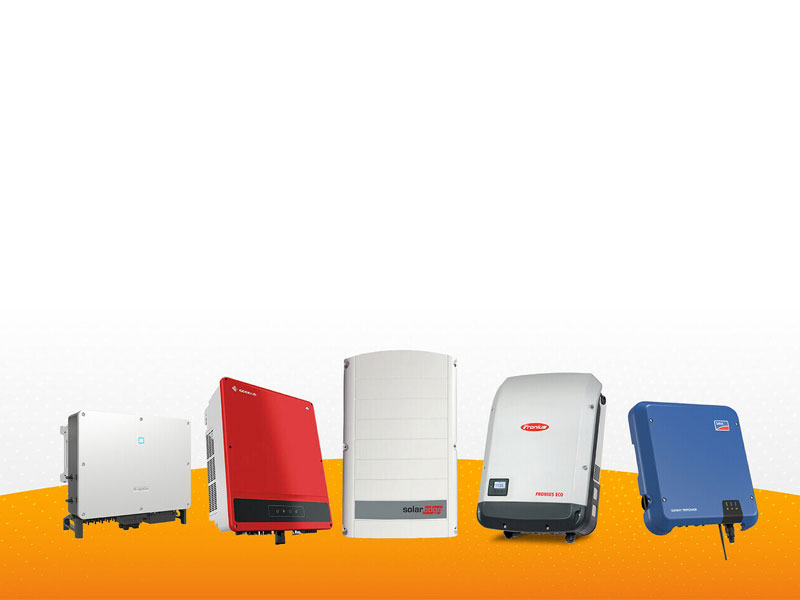
Modern inverters come in various types, including grid-tied inverters, off-grid inverters, microinverters, and string inverters, each designed for specific applications and requirements. Research continues to focus on improving inverter efficiency, reliability, and grid compatibility as the world transitions toward more sustainable and decentralized energy systems.
AC and DC current differences
AC (alternating current) and DC (direct current) are two fundamental types of electrical systems, each with distinct characteristics and applications. Here are the key differences between AC and DC electrical systems:
- Direction of Current:
- AC: In an AC system, the direction of current flow alternates periodically. The flow of electrons reverses direction in a regular cycle.
- DC: In a DC system, the current flows in one direction only. Electrons move from the negative terminal to the positive terminal of the source.
- Voltage Polarity:
- AC: The voltage in an AC system periodically changes polarity. It alternates between positive and negative values as the current direction changes.
- DC: The voltage in a DC system remains constant and has a fixed polarity.
- Energy Transfer:
- AC: AC systems are well-suited for transmitting electrical energy over long distances. High-voltage transmission lines use AC because transformers can efficiently change the voltage level for distribution and minimize energy losses.
- DC: DC systems are better suited for shorter distances and localized distribution, such as within buildings or for certain specific applications like battery-powered devices.
- Voltage Regulation:
- AC: AC voltages can be easily transformed and regulated using transformers, making it convenient for adjusting voltage levels as needed for different applications.
- DC: Voltage regulation in DC systems typically requires electronic devices like voltage regulators.
- Electromagnetic Effects:
- AC: AC systems generate electromagnetic fields that can induce currents in nearby conductors, which can be both advantageous (as in transformers) and problematic (as in electromagnetic interference).
- DC: DC systems generally have less electromagnetic interference since there is no continuous change in current direction.
- Generation and Conversion:
- AC: Most power generation in the world is based on AC systems, as it’s easier to generate AC using rotating machines like generators.
- DC: Many modern electronic devices and renewable energy sources generate DC power. However, devices that run on batteries or solar panels often need DC-to-AC inverters to convert the power for use in AC-based systems.
- Safety and Hazards:
- AC: Higher-voltage AC systems are often more hazardous to human safety due to the potential for severe electric shock.
- DC: Lower-voltage DC systems are generally considered safer for human contact but can still pose risks at higher voltages.
- Historical Context:
- AC: AC power gained prominence in the late 19th century with the development of AC distribution systems by Nikola Tesla and others.
- DC: DC systems were used in the early days of electricity but were largely replaced by AC systems due to their advantages in transmission and distribution.
In modern times, both AC and DC systems have their roles and applications. AC is dominant in large-scale power generation and distribution, while DC has gained importance in applications like electronic devices, batteries, renewable energy sources, electric vehicles, and certain specialized industrial applications.
Difference between AC and DC electrical systems
Electricity is the flow of electrons which is usually demonstrated to a student by the means of DC power. In an electrical system that uses DC power, electrons flow in a straight line such as ants carrying food to the nest. This is usually the case for devices that are battery operated. The flow of electrons flows from the batteries to the device until the batteries are depleted.
However, most larger electrical household appliances make use of Alternating current or AC. AC electricity changes directions of flow of electrons around 50 to 60 times in a second. This is also commonly referred to as 50hz or 60hz. So how does AC power gets delivered when it is constantly changing direction? If you have a light and it is connected with cabling through the wall, the cable is stuffed with electrons. When you turn on the switch for the light, the electrons are vibrating back and forth to the filament of the lights, thus, the rapid shuffling converts electrical energy into heat and allows the light to turn on. Electrons in AC electricity works on the spot and won’t require a loop to run before transporting energy.
What is an inverter?
Nicola Tesla paved the way for Alternating current which allows all our appliances to make use of AC power. Many appliances require DC power but should generate or receive power from AC sockets. Therefore, a rectifier, which is built from electrical diodes, are used in such cases to convert AC to DC power.
An inverter does the same work but in an opposite manner. For instance, a battery-operated torch or flashlight, if the battery of the flashlight is connected, DC power starts flowing around the circuit always maintaining one-directional flow. If you remove the battery, reverse its position, the DC power will still flow in a one-directional manner, but, in the opposite way. If in some way you could change the battery and reverse it 50 to 60 times in a second, you would become an inverter as you are changing the batteries Direct Current to Alternating Current going at a frequency of 50hz or 60hz.
Although, most inverters won’t work this way, however, you still get mechanic inverters which does just this. An electromagnetic switch is used in mechanic inverters which allow them to change and reverse DC directions at very high speeds. This type of DC to AC conversions by mechanic inverters are also known as, square-wave output inverters. This type of energy conversion can be damaging to some electrical equipment. Standard AC power current changes gradually from one direction to another which is known as a sine-wave. Most modern inverters can convert DC input into a stable and pure sine-wave AC output. By the use of capacitors and inductors, inverters can make output currents rise and fall moderately. Transformers can also be used alongside inverters to control and change specific Direct Current input voltages into a different Alternating Current voltage. However, the output power should always be less than the input power. An inverter and transformer can’t give more power than they receive. Some of the power gets lost in transmission due to heat as electrons flow through many electrical devices and components in the process. Even though many inverters have efficiencies of over 90%, but physics always ensure that some small form of energy went missing somewhere else in the process.
How does an inverter work?
To generate AC power from DC power, you would require a switch that can reverse DC, 50 or 60 times in a second. That is the same as swapping battery contact in and out for more than 3000 times a minute. It’s impossible to do manually.
Older mechanic inverters were used as a switching mechanism which was connected with transformers. Transformers are electromagnetic devices that change low-voltage into high-voltage Alternate power. There are two coils made from wire (primary and secondary) which are around an iron core. Usually, an electrical motor switches the DC input power back and forth in the primary. This is simply a process of reversing the contacts and generating Alternate current in the secondary. This can be compared to an electrical doorbell. When there is connected power, the switch gets magnetized, pulling it open and switching it off. A spring is used to pull back the switch into position, turning it on again and the process repeats itself.
An inverter is an electronic device that converts direct current (DC) into alternating current (AC). It’s commonly used in various applications, including solar power systems, uninterruptible power supplies (UPS), electric vehicles, and more. Here’s how an inverter works:
- Input Stage:
- The inverter receives a DC input voltage from a source such as a battery or a solar panel array. This input voltage is typically stored in the form of direct current, where the voltage remains constant with a fixed polarity.
- DC-to-AC Conversion:
- The main function of the inverter is to convert the DC input into AC output. To achieve this, the inverter uses electronic components such as transistors or insulated gate bipolar transistors (IGBTs).
- These components are switched on and off rapidly in a specific pattern, controlled by the inverter’s circuitry. This switching creates a series of voltage pulses that approximate an AC waveform.
- Pulse Width Modulation (PWM):
- The switching pattern used by the inverter is often based on a technique called pulse width modulation (PWM). In PWM, the width of the voltage pulses is varied while keeping the frequency constant. By adjusting the width of these pulses, the inverter can control the amplitude of the output voltage.
- Filtering and Shaping:
- The output of the inverter consists of a series of voltage pulses that, when averaged over time, resemble an AC waveform. However, these pulses might still have some high-frequency components that need to be smoothed out.
- To achieve a cleaner AC waveform, the inverter’s output is often passed through filters that help remove unwanted harmonics and noise. These filters can consist of capacitors and inductors.
- Output Voltage Control:
- The inverter’s control circuitry adjusts the switching pattern of the electronic components to maintain the desired AC output voltage and frequency. This control is important to ensure that the inverter’s output matches the requirements of the connected load.
- Synchronization (Grid-Tied Inverters):
- In grid-tied solar power systems, inverters need to synchronize their output with the utility grid. This involves detecting the grid’s voltage and frequency and adjusting the inverter’s output accordingly. This synchronization ensures that the power generated by the solar panels is in phase with the grid’s power.
- Protection and Safety Features:
- Inverters often include protection mechanisms to ensure the safety of the system and connected devices. These mechanisms can include overcurrent protection, overvoltage protection, and temperature monitoring.
- Advanced Features (Smart Inverters):
- Modern inverters may include advanced features like maximum power point tracking (MPPT) for solar systems, communication interfaces for remote monitoring and control, and grid support functions such as reactive power compensation and anti-islanding protection.
In summary, an inverter works by converting DC input into AC output through a combination of switching components, pulse width modulation, filtering, and control circuitry. The specific design and features of an inverter can vary depending on its intended application and the requirements of the connected system.

Overview of inverter types
If you keep switching DC on and off, it will reverse the flow of electrons the whole time. Changes of current all in one direction, then into another direction and back again is what the conclusion will be. A square wave of current flow is what will be generated from this scenario. Generally speaking, this can be identified as Alternating Current, although, it is not a smooth sine wave current which you will receive from AC powered outlets in your electrical outlets. Electrical appliances that use high wattages or raw power such as electrical heaters and kettles, don’t bother in what specific wave they receive power. They only require large amounts of electricity to function correctly. The electrical current in the means of square waves is just fine for these power-hungry devices. Other electrical components are much more specific when receiving electricity and they will require a standard smooth sine wave input to function properly and safely. Therefore, there are mainly two types of inverters, pure sine wave inverters, and modified sine wave inverters.


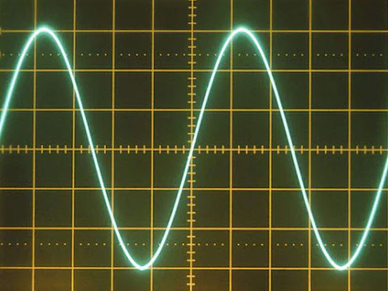
Pure sine wave inverters
A pure sine wave inverter is a type of inverter that produces an output waveform that closely resembles a pure sine wave. This type of waveform is smooth and continuous, replicating the natural waveform of the electricity supplied by utility grids. Pure sine wave inverters are designed to provide high-quality and reliable AC power, making them suitable for a wide range of sensitive electronic devices and applications.
Pure sine wave inverter features:
- High-Quality Output:
- A pure sine wave inverter produces a clean and smooth waveform similar to the AC power provided by utility companies. This high-quality output ensures compatibility with all types of AC appliances, including those that are sensitive to variations in voltage or frequency.
- Compatibility with Sensitive Devices:
- Many modern electronic devices, such as computers, laptops, audio equipment, and medical devices, require a stable and distortion-free AC power supply to operate correctly. Pure sine wave inverters provide the level of power quality needed by these sensitive devices, preventing potential issues like overheating, malfunctions, or data loss.
- Less Noise and Interference:
- Pure sine wave inverters generate less electrical noise and electromagnetic interference compared to other types of inverters that produce modified sine wave or square wave outputs. This is important for devices like radios and audio equipment that can be affected by interference.
- Efficiency and Performance:
- Some devices, particularly those with motors or variable speed drives, may operate more efficiently and run cooler when powered by a pure sine wave. Additionally, appliances that require a specific voltage level to function optimally will work better with a pure sine wave supply.
- Smooth Start-Up:
- Devices that require a smooth and gradual start-up process, such as refrigerators and air conditioners, tend to perform better with a pure sine wave supply. Modified sine wave or square wave inverters can sometimes cause such devices to struggle during start-up.
- Reduction of Audible Noise:
- Some devices, particularly those with transformers or inductive loads, can produce an audible buzzing sound when powered by modified sine wave inverters. Pure sine wave inverters can help minimize or eliminate this issue.
- Compatibility with Solar Power Systems:
- Pure sine wave inverters are often preferred for solar power systems. This is because solar panels generate DC power, which is converted into AC power by the inverter. A pure sine wave inverter ensures that the AC power generated is of high quality and can be seamlessly integrated with the grid or used by sensitive devices.
While pure sine wave inverters offer numerous benefits, they are generally more complex and expensive to manufacture compared to modified sine wave or square wave inverters. The choice between inverter types depends on the specific needs of the application and the types of devices that will be powered by the inverter.
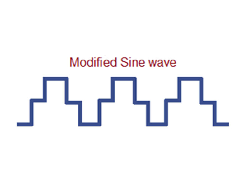
Modified sine wave inverters
A modified sine wave inverter is a type of inverter that produces an AC output waveform that is a modified approximation of a sine wave. Unlike a pure sine wave inverter that generates a smooth and continuous waveform, a modified sine wave inverter produces a waveform that consists of a series of steps or stair-like segments. Each segment corresponds to a certain voltage level, and the transitions between these voltage levels create the modified sine wave shape.
Modified sine wave inverter features:
Output Waveform:
- The output waveform of a modified sine wave inverter is composed of a series of square or rectangular voltage pulses. These pulses are switched on and off in a pattern to approximate the shape of a sine wave. However, the waveform is not as smooth and continuous as that of a pure sine wave.
- Compatibility with Devices:
- Modified sine wave inverters are often less expensive to produce than pure sine wave inverters. They are suitable for powering many common household appliances and devices, such as lights, fans, heaters, and basic electronics.
- Compatibility Issues:
- Some devices may not operate optimally or might even malfunction when powered by a modified sine wave inverter. Devices with motors, transformers, capacitive loads, and certain types of sensitive electronics might experience issues due to the waveform’s characteristics.
- Audible Noise and Heating:
- Devices powered by modified sine wave inverters, especially those with inductive or capacitive components, can produce audible buzzing sounds or exhibit increased heating. This is because the abrupt transitions in the waveform can create harmonics and electrical noise.
- Efficiency and Performance:
- While modified sine wave inverters are less efficient than pure sine wave inverters, they can still provide basic power for various appliances. Some appliances, like resistive heaters and incandescent lights, are less sensitive to waveform quality and can work reasonably well with a modified sine wave.
- Cost-Effectiveness:
- Modified sine wave inverters are often chosen for applications where cost is a significant factor. They can provide a more affordable solution for basic power needs, especially in situations where sensitive electronics are not being used.
- Simplified Design:
- The circuitry of a modified sine wave inverter is generally simpler than that of a pure sine wave inverter, which can contribute to lower production costs.
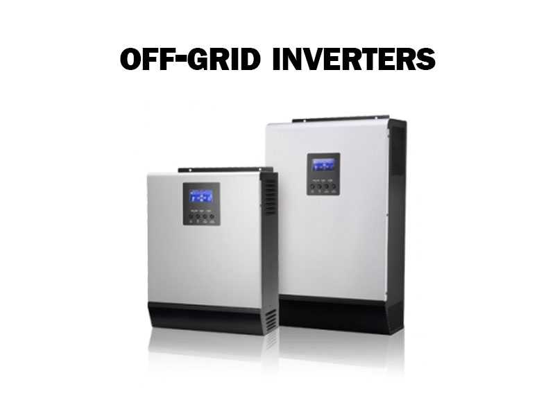
Off-grid inverter
A large variety of inverters work as standalone inverters or units, which make use of batteries for energy storage and are completely off the grid and independent from Eskom. An off-grid inverter, also known as a standalone inverter, is an essential component in off-grid solar power systems or other independent power setups where a reliable source of AC power is required without a connection to the utility grid. Off-grid systems are commonly used in remote areas, cabins, boats, RVs, and locations where grid electricity is unavailable or impractical. Most off-grid inverter sold can be integrated with Eskom to allow the flow of AC current into the inverter to recharge batteries and accommodate for flow-through power to accommodate electrical loads in a home. However, off-grid inverters cannot synchronize with the Eskom grid to feed electricity back into the grid, not can they feed non-essential loads apart from essential loads.
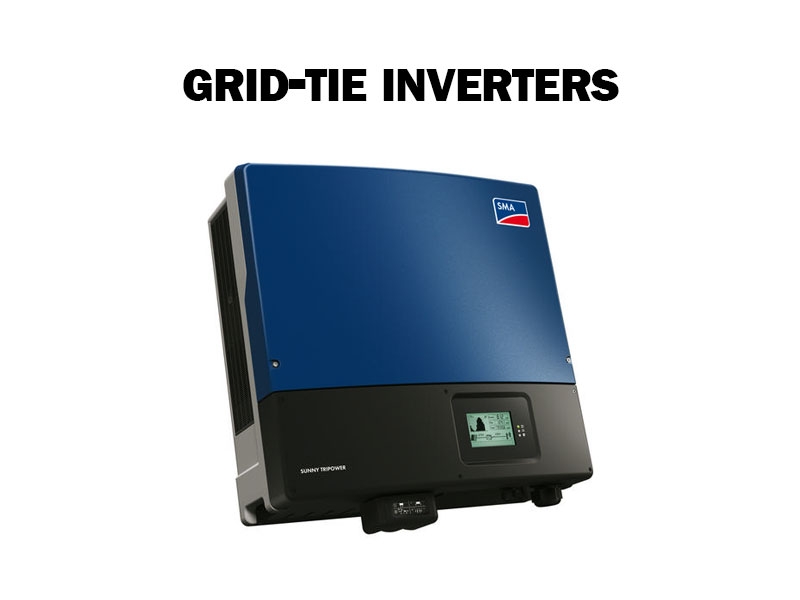
Grid-tied Inverter
Grid-ties inverters, which are also known as interactive inverters, are manufactured and designed to be connected to the electricity grid Eskom provides. They are connected to the grid at all times and are usually installed with solar panels to save on electricity usage but also if there is unused energy generated by the solar panels, the energy is sent back into the grid at the correct frequencies and voltages. Grid-tied inverters are an excellent option if you want to provide your own electricity for your home. However, grid-tied inverters are not a great solution for going off the Eskom grid. A battery backup storage will be required if you want to store energy in times of load shedding. In case of load shedding or power outages during the night, the grid-tied inverter powers off. This will leave you sitting in the dark without power.
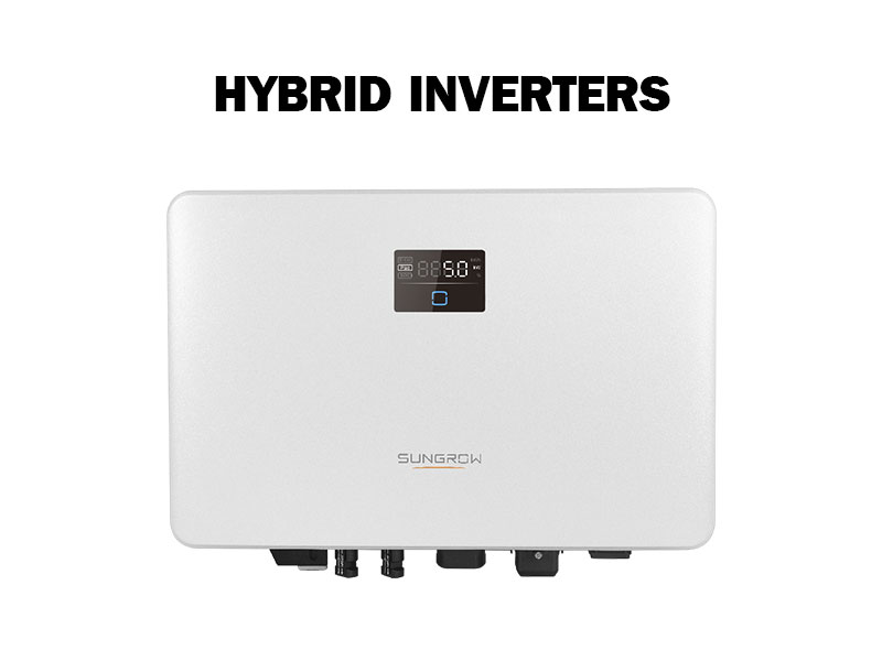
Bi-directional inverters (Hybrid inverters)
A bi-directional inverter, also known as a hybrid inverter or dual-mode inverter, is an advanced type of inverter that has the capability to convert power in two directions—converting direct current (DC) to alternating current (AC) and vice versa. This means that a bi-directional inverter can operate in both grid-tied mode and off-grid mode, allowing it to interact with both external power sources (like utility grids) and energy storage systems (like batteries).
Here's an explanation of hybrid inverters
Grid-Tied Mode: In grid-tied mode, a bi-directional inverter works similarly to a standard grid-tied inverter. It converts DC power generated by sources like solar panels into AC power that can be fed back into the utility grid. This process is known as “feeding power into the grid” or “grid export.” When the power generated by the solar panels exceeds the immediate consumption of the connected load, the excess power is sent back to the grid, potentially earning the system owner credits or compensation through net metering arrangements.
- Off-Grid Mode: In off-grid mode, a bi-directional inverter can function as a typical off-grid inverter, converting DC power stored in batteries into usable AC power for household appliances and devices. This is especially useful in situations where there’s no access to the utility grid, such as in remote areas or during power outages.
- Battery Charging and Discharging: One of the key features of a bi-directional inverter is its ability to manage both battery charging and discharging. When in grid-tied mode, excess solar power can be used to charge batteries, storing energy for later use. In off-grid mode, the inverter can convert stored energy from batteries into AC power to meet the electrical demands of the household.
- Energy Management: Bi-directional inverters often include advanced energy management features. They can optimize energy usage by determining when to draw power from the grid, when to use stored battery energy, and when to use energy generated by renewable sources. This helps reduce electricity bills and increase self-consumption of generated power.
- Backup Power: Some bi-directional inverters offer the capability to provide backup power during grid outages. When the utility grid goes down, the inverter can switch to off-grid mode and utilize energy stored in batteries to power essential loads.
- Smart Grid Integration: Bi-directional inverters can play a role in smart grid integration. They can respond to grid signals, such as time-of-use pricing or demand response signals, by adjusting their operation to take advantage of cheaper electricity rates or to support grid stability.
- Hybrid Systems: Bi-directional inverters are often used in hybrid energy systems that combine renewable energy sources (like solar or wind) with energy storage (like batteries) and possibly a backup generator. These systems provide greater flexibility and reliability compared to single-mode systems.
What is an inverter like?
Inverters can weigh heavy and are usually too heavy for some people to carry comfortably. A battery pack included with the inverter can add even more weight, especially if the inverter is standalone or hybrid. Inverters produce large amounts of heat, therefore, cooling fans are installed in correlation with big heat sinks which can easily be spotted. Inverters vary in the amounts of electricity they can produce, just like specific household appliances vary in electricity consumption. It is a best practice to always use an inverter which is about a quarter rated higher maximum power than the electrical components you would like to power. Therefore, allowing freezers, fridges and fluorescent lamps to consume maximum power when they are turned on. Inverters are not designed to run at full power or peak power for long periods, although, inverters can run at peak power for short intervals of time.
UPS or uninterruptible power supply unit
Inverters can be used to provide power in power outages or during load shedding and can be called a UPS or uninterruptable power supply unit. A common UPS system stores rechargeable DC energy in battery storage. When the AC power of the home is available, the batteries can be charged by DC power from AC power, by the means of a transformer and rectifier circuit. If the home’s AC power goes off, you will have DC power ready at your disposal. Your appliances require AC power, therefore, the batteries transfer DC energy to the inverter which then converts the DC power from the batteries to usable AC power.
UPS inverter systems
A UPS (Uninterruptible Power Supply) inverter system is a combination of devices that provides backup power and protection against power disruptions, such as blackouts, voltage fluctuations, and surges. It ensures that critical equipment and devices remain operational even when the main power source fails. The system typically consists of the following components:
- Inverter:
- The core component of a UPS inverter system is the inverter itself. It converts DC power stored in batteries into usable AC power. The inverter switches to battery power almost instantaneously when a power outage is detected, ensuring that connected devices continue to receive power without interruption.
- Batteries:
- Batteries are an essential part of a UPS inverter system. They store the energy that will be used to provide backup power during outages. The capacity and type of batteries used determine how long the system can sustain power to connected loads.
- Charger:
- A charger is responsible for replenishing the batteries’ energy when the main power is available. It ensures that the batteries are fully charged and ready to provide backup power when needed.
- Automatic Voltage Regulator (AVR):
- Many UPS inverter systems incorporate an AVR to regulate the input voltage from the main power source. An AVR helps protect connected devices from voltage fluctuations, ensuring a stable voltage supply even when the input voltage varies.
- Control Circuitry:
- The control circuitry in the UPS manages various functions, including monitoring the input power status, switching between mains power and battery power, and managing battery charging and discharging.
- Display and Interfaces:
- A UPS inverter system often includes a display panel or interface to provide real-time information about the system’s status, battery charge level, and other parameters. Some systems also offer remote monitoring and control options through software or network connections.
- Output Sockets and Outlets:
- The UPS provides AC output sockets or outlets to which critical devices can be connected. These outlets ensure that important equipment, such as computers, servers, networking devices, and medical equipment, remain powered during outages.
- Types of UPS Inverter Systems:
- There are different types of UPS inverter systems, classified based on the amount of time they can provide backup power:
- Offline/Standby UPS: Switches to battery power only when the main power fails. It offers basic protection with minimal power interruption.
- Line-Interactive UPS: Includes an AVR to regulate input voltage and provides smoother transitions between battery and mains power.
- Online/Double Conversion UPS: Constantly converts incoming AC power to DC and then back to AC. Offers the highest level of protection and can provide continuous power during outages.
- There are different types of UPS inverter systems, classified based on the amount of time they can provide backup power:
UPS inverter systems are widely used in various settings, including homes, offices, data centers, healthcare facilities, and industrial environments. Their ability to provide reliable backup power helps prevent data loss, equipment damage, and disruptions in critical operations during power disturbances.